

When we talk about plastic table moulds, cooling system optimization isn’t just a minor detail—it’s the difference between a mould that runs for years with consistent quality and one that causes endless delays, defects, and lost revenue. As a supplier of plastic table moulds, I’ve spent countless hours troubleshooting why some moulds produce perfect, warp-free tables on the first 100 shots and others struggle with sink marks, uneven cooling, and cycle times that eat into production capacity. Today, I want to share the practical, science-backed strategies we use to optimize cooling systems for every type of table mould we build, from simple plastic square table mould to more complex adjustable designs, because every table mould has unique cooling needs.
Let’s start with the basics: why cooling matters for plastic table manufacturing. When molten plastic is injected into a mould cavity, it needs to solidify uniformly to take the desired shape. For a plastic table—whether it’s a sturdy square model, a sleek round version, or an adjustable model for different heights—thicker sections (like table legs or the outer rim) cool slower than thinner areas (the tabletop surface). If the cooling system can’t remove heat evenly, the thicker sections will shrink more as they cool, causing warping, sink marks, or even incomplete curing. This not only ruins parts but also slows down cycle times: the longer a mould stays closed waiting for plastic to solidify, the fewer parts you can make per hour. For high-volume production, that’s a direct hit to your bottom line.
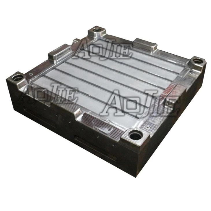
First on our list is optimizing cooling channel design, and this is where we tailor every choice to the specific table mould we’re working with. For a plastic round table mould, the circular shape presents a unique challenge: the outer rim is thicker than the central tabletop, so a straight, single cooling line won’t cut it. We use conformal cooling channels here—channels that follow the exact contour of the mould cavity, instead of being drilled straight through. For round tables, that means placing small, evenly spaced channels along the outer rim and a central cross-shaped channel to target the thicker central support. This ensures that both the rim and the center cool at almost the same rate, eliminating sink marks where the rim meets the tabletop. For comparison, a square table’s corners are another high-stress area—they cool faster than the flat sides, so we add small, localized cooling pins at the corners of a plastic square table mould to draw out extra heat and balance the cooling rate.
What about mould components that aren’t the tabletop itself? Table legs and connectors are critical parts that often get overlooked in cooling design. For a plastic table leg cover plastic injection mould, the leg cover has a hollow interior that can trap heat, leading to long cycle times and warped covers that don’t fit snugly onto table legs. We add small baffles inside the cooling channels for these components—baffles are metal inserts that force water to flow through the center of the channel, instead of just along the walls. This increases the turbulence of the cooling water, which is key for heat transfer. Without baffles, water would follow the path of least resistance along the channel walls, leaving the center of the channel (and the thickest part of the mould component) with stagnant, warm water that does almost no cooling. For even more complex parts like the plastic table leg connector injection mould, which has multiple small holes and a thin, precision-molded body, we use additive manufacturing (3D printing) for the mould core to create fully conformal cooling channels that wrap around every protrusion and hole. This would be impossible with traditional drilling, which can only make straight, intersecting channels, and it cuts cycle times for these small parts by up to 25% in our testing.
Next, cooling fluid selection and management are often underestimated, but they have a huge impact on performance. Most mould makers use plain tap water as coolant, but this is a mistake. Tap water has minerals that can build up scale inside cooling channels over time—scale acts as an insulator, reducing heat transfer by up to 30% in some cases. For a mould that runs 24/7, that adds up quickly: your cooling system becomes less effective, cycle times get longer, and you start seeing more defects as the mould doesn’t cool evenly. We use deionized (DI) water for all our moulds, and we recommend that our clients do the same. DI water doesn’t leave mineral deposits, so the cooling channels stay as efficient as the day they were built. We also add a small amount of corrosion inhibitor to the DI water—moulds are made of steel or aluminum, and even small amounts of water can cause rust over years of use. A rusted channel has rough walls, which slows water flow and creates dead spots where heat builds up.
Then there’s flow rate and pressure control. It’s not just about using the right fluid—it’s about making sure it flows fast enough. The rule of thumb for cooling channels is that the flow rate should be high enough to create turbulent flow, not laminar flow. Laminar flow is when water moves in smooth, parallel lines through the channel—this doesn’t mix heat well, so it’s ineffective for removing heat from the mould wall. Turbulent flow is chaotic, mixing the water and carrying heat away much faster. To calculate the required flow rate, we use the Reynolds number: for cooling channels, we aim for a Reynolds number of 10,000 or higher. For a standard 10mm diameter cooling channel, that means a flow rate of around 1 liter per minute. If the flow is too low, you can increase the channel diameter slightly or add more parallel channels. For the plastic adjustable table mould, which has two separate cavities (one for the tabletop, one for the adjustable height mechanism), we split the cooling system into two independent loops. This lets us adjust the flow rate to each cavity based on its thickness: the tabletop needs a higher flow rate, while the thinner adjustable parts can run on a lower rate, saving energy without sacrificing quality.
Temperature control is another key piece of the puzzle. The inlet and outlet temperatures of the cooling water make a big difference in uniform cooling. If the inlet water is too warm, the mould won’t cool enough, leading to long cycle times. If the temperature difference between inlet and outlet is too large, that means one side of the mould is cooling much faster than the other, causing warping. We recommend keeping the temperature difference between inlet and outlet below 3°C. For example, if you set your chiller to an inlet temperature of 18°C, the outlet should be no higher than 21°C. For large moulds like big square tables, we use multiple chillers or a temperature control unit (TCU) with zone temperature control. That way, we can set different temperatures for different sections of the mould: the outer rim of a large table cools faster, so we can set its inlet temperature to 16°C, while the central tabletop can run at 18°C to balance the cooling rate. This eliminates the warping that often happens when a single temperature is used for the entire mould.
We also can’t forget about mould material selection, which works hand in hand with the cooling system. If a mould is made of a material with low thermal conductivity, even the best cooling channels won’t transfer heat efficiently. For thick-walled table moulds, we use pre-hardened tool steel with a thermal conductivity of around 45 W/m·K, which is much higher than standard steel. For smaller, precision parts like table leg connectors, we use aluminum moulds—aluminum has a thermal conductivity of around 205 W/m·K, which is more than four times higher than steel. This means heat is pulled from the molten plastic into the mould much faster, so the cooling system doesn’t have to work as hard. When we work on a plastic table leg cover plastic injection mould, for example, an aluminum core cuts the cycle time by 15% compared to a steel core, because heat spreads through the aluminum and reaches the cooling channels faster.
Maintenance is the final, most important step to keeping a cooling system optimized over time. No matter how well-designed your cooling system is, if you don’t maintain it, it will lose efficiency. We give all our clients a simple maintenance schedule: every three months, flush the cooling channels with a descaling solution to remove any mineral buildup from the water. Every six months, check the flow rate of each channel—if a channel is flowing 20% less than the original rate, there’s probably a blockage that needs to be cleared. We also recommend checking the chiller’s temperature readings monthly to make sure they’re within the desired range. In our own factory, we follow this schedule for every mould we use, and we’ve seen cycle times stay consistent for up to 5 years, compared to moulds that only get occasional flushing and see cycle time increases of 10-15% in the same period.
Let’s put this all together with a real example. Last year, a client reached out to us with a plastic square table mould that was producing 10% defective parts, with cycle times of 45 seconds per shot. They’d been using the mould for two years and thought they needed to replace it. We ran a thermal scan of the mould and found that the corners were 8°C cooler than the flat sides, and the central rim was 5°C hotter, causing sink marks. We adjusted the cooling channels by adding two small cooling pins at each corner, switched from tap water to DI water with corrosion inhibitor, and increased the flow rate to create turbulent flow. After the changes, the defect rate dropped to less than 1%, and cycle times went down to 32 seconds—an increase in production of over 40% without any investment in new equipment. That’s the power of cooling system optimization, and it’s exactly what we do for every client, no matter what type of table mould they have.
At the end of the day, optimizing a plastic table mould’s cooling system isn’t a one-size-fits-all process. It requires matching the cooling channel design, fluid type, flow rate, temperature control, mould material, and maintenance schedule to the specific mould’s size, shape, and use case. Whether you’re running a plastic round table mould for outdoor use, a plastic adjustable table mould for home furniture, or small moulds for table legs and covers, paying attention to these details will help you produce higher-quality parts, reduce defects, and boost production efficiency.
If you’re looking to improve the performance of your current plastic table moulds or invest in new moulds with optimized cooling systems, our team is here to help. We have years of experience designing and building a full range of plastic table moulds, including the plastic square table mould, plastic adjustable table mould, plastic table leg connector injection mould, plastic round table mould, and plastic table leg cover plastic injection mould, all with cooling systems tailored to deliver maximum efficiency and quality. Reach out to our team to discuss your needs and get a custom solution for your production.

References
- Rosato, D. V., & Rosato, M. G. (2000). Injection Molding Handbook (3rd ed.). Springer.
- Kazmer, D. O. (2007). Injection Mold Design Engineering. Hanser Publications.
- Gilbert, M. (2015). "Conformal Cooling in Injection Molding: Design and Applications." Journal of Injection Molding Technology, 19(2), 45-52.
- Baird, D. G., & Collias, D. I. (2014). Polymer Processing: Principles and Design (2nd ed.). Wiley.
- International Organization for Standardization. (2018). ISO 10360-8:2018, Geometrical Product Specification (GPS) - Acceptance and Verification of Coordinate Measuring Machines - Part 8: CMMs for Measurement of Form.